Oxygen sensors are crucial for ensuring optimal vehicle performance and compliance with environmental standards. The 1999 Dodge Dakota truck utilizes advanced technology with two oxygen sensors, making regular maintenance and timely replacement essential. For fleet managers, trucking company owners, construction and mining enterprise operators, and logistics service providers, understanding how to handle oxygen sensor issues directly impacts fleet efficiency and operational costs. This article will focus on identifying the oxygen sensor, selecting the correct replacement part, the necessary tools for installation, a step-by-step guide for replacing the sensor, and the potential repercussions of operating with a faulty oxygen sensor. Each chapter will equip you with the knowledge needed to maintain your fleet effectively and economically.
Reading the Gatekeeper: Identifying and Replacing the Oxygen Sensor on a 1999 Dodge Dakota
The oxygen sensor is one of those small, unassuming parts that quietly keeps a modern engine honest. It sits in the exhaust stream, watching the oxygen content as exhaust gases surge past the engine’s combustion chamber. The data it sends to the engine control module (ECM) is used to fine-tune the air-fuel ratio in real time. When the sensor is working, the engine breathes cleanly, fuel economy stays steady, and emissions stay within the limits that matter to both state regulations and your catalytic converter. When it drifts or fails, the ECM can’t read the exhaust properly, and the mixture can swing lean or rich. That misbalance often shows up as a check engine light accompanied by an OBD-II code in the P0130 through P0141 range. For a 1999 Dodge Dakota, the path back to reliable operation is usually straightforward: identify the right sensor, replace it with a proper sensor, and allow the system to relearn. Repairing a failed oxygen sensor is not a practical option in most cases; these sensors are complex, exposed to high heat, and designed to be replaced rather than repaired. Understanding where to look and how to proceed can save time, money, and the frustration of chasing symptoms that won’t go away without a proper fix.
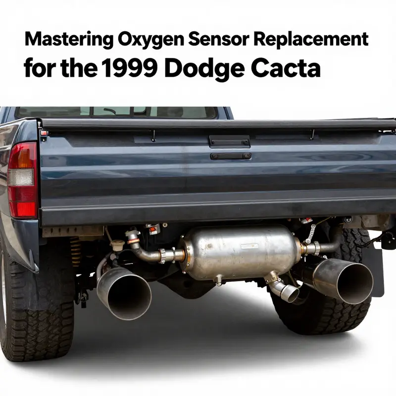
On the Dakota of this era, there are two oxygen sensors that you’ll typically encounter. The primary sensor, located upstream, sits before the catalytic converter and monitors the air-fuel mixture entering the converter. The secondary sensor, downstream, is after the catalytic converter and checks the converter’s performance. The practical implication of this arrangement is simple: if the trouble code points to Sensor 1, you’re dealing with the upstream sensor; if it mentions Sensor 2, the downstream sensor is the one to address. Locating these sensors is usually not difficult, but confidence matters. The upstream sensor tends to sit higher in the exhaust manifold or just on the exhaust pipe where it meets the manifold. The downstream sensor lies further back, closer to the exhaust tail, after the catalytic converter. In a typical Dakota, the upstream sensor is the one that monitors the air-fuel mixture as it enters the catalytic converter, while the downstream sensor watches the converter’s efficiency by evaluating the exhaust downstream from the catalyst. Familiarizing yourself with this layout helps prevent misidentification, which can lead to wasted time and the wrong part being ordered.
Identifying the correct sensor for replacement begins with a careful check of the vehicle’s details. Confirm the exact year and engine size of the Dakota, because a 3.9L V6 and a 5.2L or 5.9L V8 can have slightly different sensor arrangements or harness routing. Once you’ve confirmed the engine, you can cross-verify using a data source or parts catalog that matches your VIN. In practice, most Dakota owners find it easiest to search for an oxygen sensor that is compatible with the year and engine specification and then filter for an upstream or downstream position based on the code reported by the OBD-II scanner. When you’re ready to buy, you’ll want a high-quality sensor that is either OEM-equivalent or from a reputable aftermarket supplier. The goal is an exact fit, proper electrical connector, and a sensor that can handle the heat and contaminants of a gasoline exhaust stream over thousands of miles. The path forward is clear: do not attempt to repair a sensor that has failed or become contaminated; the risk of persisting poor readings, increased emissions, and potential damage to the catalytic converter is simply too high. A replacement aligned with the vehicle’s specs is the reliable course.
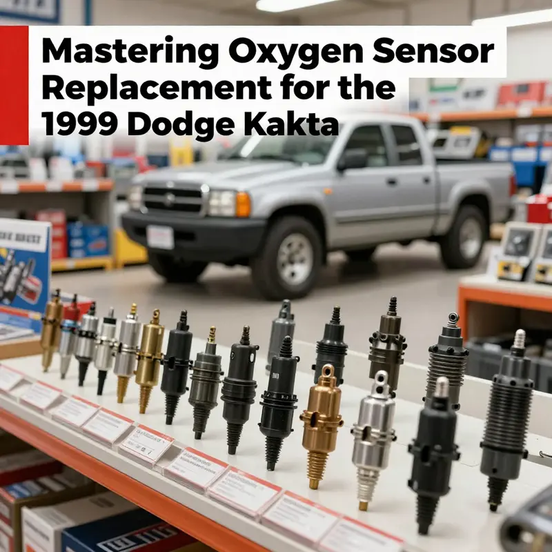
Choosing the right replacement part means balancing reliability, fit, and compatibility. Instead of chasing the exact brand name, focus on an OEM-equivalent sensor designed for your Dakota’s year and engine. An ideal replacement will match the electrical connector type, the thread size and length, and the heater circuit if the sensor is heated. The goal is a plug-and-play fit that requires no jury-rigged wiring or soldering. When you order, you’ll want to verify compatibility with your specific Dakota model, ideally by using your VIN and the engine code. If the catalog shows separate upstream and downstream options, confirm which position is involved by reading the fault code or by tracing the exhaust path. The importance of correct positioning cannot be overstated; a mismatch can cause poor engine performance and continued emissions problems, even if the sensor itself is new.
Once the new sensor arrives, the installation is largely a mechanical procedure with one key caveat: treat the process methodically and avoid forcing anything. First, give the engine and exhaust system ample time to cool. A hot manifold or pipe can burn you and may expand fittings in ways that make removal harder later. Locate the sensor by following the exhaust pipe to the point where it threads into the manifold or a sensor mounted on the pipe downstream of the manifold. It’s worth noting that some Dakota configurations route the sensor with a protective heat shield or wrap, so remove any shielding cautiously if it obstructs access.
A small detail can save you a lot of trouble. If the old sensor is stubborn, apply a penetrating oil to the sensor threads and allow a few minutes for the oil to creep into the joint. This step can be the difference between a quick, clean break and a seized, corroded bolt that resists wrenches. When you’re ready, use an oxygen sensor socket—a tool sized to fit the sensor’s hex and to reach the restricted space around the exhaust pipe. Avoid using a standard adjustable wrench, which can strip the sensor’s hex or the connector. With the old sensor unscrewed, you can compare the new unit against the old one to ensure the threads and connector angles match. If the new sensor threads smoothly by hand and the connector aligns with the loom, you’re in good shape to tighten with a wrench. When tightening, apply steady, even torque and avoid overtightening, which can damage the sensor threads and potentially crack the exhaust housing.
After the sensor is installed, reattach the electrical connector securely. A loose connection is a common cause of persistent sensor fault codes, so double-check both the physical connection and the locking mechanism. With the sensor in place, the next step is to clear the trouble codes using an OBD-II scanner. This resets the ECM’s fault memory so the system can begin the relearning process. Once the codes are cleared, you’ll want to drive the vehicle under normal operating conditions to let the ECM observe the new sensor’s data and reestablish a closed-loop air-fuel management. Depending on the vehicle, this relearning can take a few drive cycles, during which you may notice the engine returning to a steadier idle and the fuel economy stabilizing.
The straightforward path from diagnosis to replacement has several practical consequences for long-term maintenance. First, replacing a failed oxygen sensor helps restore proper air-fuel balance, which directly affects fuel economy and emissions. A failing upstream sensor can cause the engine to run rich or lean at different throttle positions, leading to irregular idle, reduced acceleration, and fluctuating fuel economy. A failing downstream sensor doesn’t just affect emissions; it can mask catalytic converter issues by failing to provide a valid efficiency signal to the ECM. In either case, a timely replacement typically resolves the root problem and allows the exhaust system to perform as designed. It’s important to remember that cleaning a failed sensor is not a remedy. Contaminants or irreversible sensor degradation will not be undone by simple cleaning; the sensor’s encapsulated sensors and heater elements have been compromised, and the only reliable fix is installation of a proper replacement.
As you consider how to frame the repair work within your broader vehicle maintenance plan, it can be helpful to think about the ongoing costs and scheduling. A practical approach is to incorporate sensor replacement into a routine maintenance plan, especially for vehicles sold years ago where emissions components have a finite service life. A sensible budgeting approach helps you prepare for the potential of other components that share the same environment, such as the exhaust system and catalytic converter. For a more strategic look at keeping a truck in solid condition, you may want to review guidance on routine maintenance budgeting, which offers a framework for predicting costs, prioritizing repairs, and planning ahead rather than reacting to unexpected failures. This mindset supports not only the current oxygen sensor replacement but also the broader health of the truck’s engine and emissions systems. Budgeting for Routine Truck Maintenance.
For readers seeking a deeper, model-specific reference, trusted service manuals provide step-by-step procedures tailored to your Dodge Dakota. These manuals walk through sensor identification, removal, and replacement with attention to the factory tolerances and torque specifications. If you want to corroborate the process with an external, authoritative guide, consult reputable automotive references such as AllData DIY, which document OEM procedures and diagrams for vehicles of this era. External guidance can help you confirm wiring harness routing, connector types, and any vehicle-specific quirks that might appear during replacement. AllData DIY is a solid resource to cross-check your work as you wrap up the project and start the test drive. External reference: https://www.alldatadiy.com/.
The Right Fit Over Quick Fix: Navigating Replacement Oxygen Sensors for a 1999 Dodge Dakota
When a 1999 Dodge Dakota shows a fault code tied to the oxygen sensor, the urge to “just fix it” can be strong. But oxygen sensors are intricate, exposed to extreme heat and corrosive exhaust, and they rarely respond to cleaning or improvised repairs. The vehicle’s control system relies on precise signals from these sensors to meter fuel, control ignition timing, and manage emissions. For most Dakota owners, the reliable path is clear: replace the sensor, not attempt a repair. This approach secures proper fuel economy, reduces emissions, and protects the catalytic converter from unburned fuel or excessive heat. In practice, this means understanding that the Dakota uses two sensors in most configurations—an upstream sensor before the catalytic converter and a downstream sensor after it. Each one plays a distinct role in the fuel-trim and catalyst efficiency feedback loops. If the diagnostic system points to a problem with the upstream sensor, it indicates a need to verify or replace Sensor 1. If the code denotes Sensor 2, the downstream position is implicated. The naming can be technical, referring to bank 1 and sensor 1 or bank 1 and sensor 2, depending on the engine configuration. The important point for owners is this: the codes and the positions tell you which sensor to source and install, not whether you should attempt a repair with improvised tools. The practical consequence of misinterpreting the codes is simple but costly—continued misbehavior of the fuel mixture, degraded emissions, and undue stress on the catalytic converter. With this in mind, the chapter that follows guides you through selecting the correct replacement sensor and implementing a reliable installation, keeping the vehicle out of the shop and back on the road with confidence. To explore broader maintenance philosophy and practical repair wisdom, you can visit the MasterTruckRepair blog for ongoing guidance and community-tested tips that stay close to the practical realities of truck ownership. https://mastertruckrepairllc.com/blog/.
Identifying the right sensor begins with a clear map of the Dakota’s exhaust side. The upstream sensor sits closer to the engine and monitors the air-fuel mixture entering the catalytic converter. The downstream sensor sits after the converter and evaluates how effectively the catalyst is working. Understanding this distinction is essential because it determines which sensor you order. On many 2.5L, 3.9L, or 5.2L Dakota engines, there are two sensors with distinct locations. When you pull a code such as P0130 through P0141, the code description will usually point you to Sensor 1 or Sensor 2, but the exact labeling depends on the diagnostic tool and the vehicle’s emission control system. Regardless of the labeling, the fix remains consistent: replace with a sensor designed for the Dakota’s specific year, engine, and bank location. The decision to replace rather than repair is grounded in material science and electronics. Exposure to high exhaust temperatures, the repeated heating and cooling cycle, and the sensitive ceramic element inside the sensor make repair impractical. A workaround may temporarily alleviate symptoms but will not restore the sensor’s accuracy or longevity. The vehicle’s computer relies on accurate data to function; a degraded signal leads to an overrich or lean condition, wasting fuel and pushing the catalytic converter toward premature aging.
Choosing the replacement sensor involves a few disciplined steps. First, confirm the sensor’s location by engine size and by bank numbering—these details determine the correct upstream versus downstream designation. Then, decide between OEM-grade sensors and high-quality aftermarket equivalents. OEM-grade parts offer a direct fit and the most predictable behavior, but quality aftermarket sensors can meet or exceed OEM performance when sourced from reputable suppliers. The goal is compatibility with the Dakota’s exhaust layout and the vehicle’s OBD-II expectations. In this context, you will want a sensor designed to withstand the Dakota’s operating temperatures and the torque limits of the sensor’s mounting threads. It is worth noting that some owners prefer buying a kit that includes both the upstream and downstream sensors. While this may increase upfront cost, it guarantees both positions are matched to your engine’s exact specifications and can simplify the replacement process when both sensors show wear or when a persistent code points to multiple failures. A dual-pack approach is particularly practical for vehicles approaching higher mileage, where sensor aging tends to occur in tandem. When shopping, many online automotive marketplaces offer compatibility filters. These filters help you confirm the sensor matches the Dakota’s engine size and location. Always cross-check the vehicle’s VIN, engine code, and the sensor’s location before purchasing. The goal is to secure an OEM-quality sensor or a trusted aftermarket part that is explicitly stated to fit the 1999 Dakota. Avoid any guesswork that implies a “universal” sensor will work without confirming the exact upstream or downstream position.
The sourcing process benefits from a mindful approach to compatibility and warranty. Platforms that provide clear compatibility data allow you to verify that the sensor corresponds to the Dakota’s year range (1997–2000 models commonly share similar sensor configurations) and engine variants. A robust purchase strategy includes confirming the sensor’s electrical connector type, thread size, and heat shielding if applicable. It is also prudent to verify whether the replacement comes with a warranty and what it covers, as sensors can fail early through no fault of the user if the part is defective. When you undertake this sourcing task, remember that the Dakota’s emission system rewards precise, dependable parts. The cleaner the signal the sensor sends, the better the computer can regulate fuel delivery and exhaust gas composition. In other words, the right sensor helps you achieve better fuel economy, lower emissions, and smoother engine performance. To refine your search and learn more about practical truck maintenance, you can visit the MasterTruckRepair blog for a broad spectrum of maintenance topics and hands-on guidance. https://mastertruckrepairllc.com/blog/.
Once you have the right sensor in hand, the installation is straightforward but requires attention to detail. Before you begin, let the engine cool completely. Locate the sensor or sensors on the exhaust manifold or pipe, depending on the configuration. Apply a light coat of penetrating oil to the threads if the sensor is stubborn, but avoid letting oil contact the sensor’s sensor tip or the electrical connector. Using the correct oxygen sensor socket (usually 7/8 inch or 22 millimeters) helps prevent rounding the hex. Remove the old sensor by turning it counterclockwise, taking care not to twist the wiring harness. If the sensor proves resistant, give it a few minutes and reapply oil, then attempt removal again. When the old sensor is out, compare it with the new unit to confirm the thread pitch and length match. Install the new sensor by hand first to avoid cross-threading, then tighten with a wrench until snug. Avoid overtightening, which can strip threads or damage the exhaust mounting. Reconnect the electrical connector securely, ensuring a firm lock that resists road vibration. After installation, clear the stored trouble codes with an OBD-II scanner. Finally, take the Dakota for a cautious test drive to allow the engine control module to relearn fuel trims and sensor data. The vehicle may run slightly differently until the system stabilizes, and the check engine light should stay off if the sensor is functioning correctly. If it returns, recheck the installation, connectors, and wiring harness for any signs of damage or looseness.
The broader context of replacing an oxygen sensor extends beyond a single repair. Addressing sensor faults promptly helps maintain engine efficiency and protects the catalytic converter from damage caused by rich or lean misfires. It also avoids the risk of a cascading failure that can occur when emission control systems operate outside their designed parameters. In the long run, choosing the correct sensor and installing it properly is a step toward reliable, predictable performance that can save money and time. To keep your Dakota in good shape between sensor replacements, stay engaged with routine maintenance, including inspecting exhaust components for leaks, testing the oxygen sensors periodically, and monitoring fuel economy as a practical indicator of sensor health. For readers seeking a broader perspective on maintenance planning and budget-friendly upkeep, the MasterTruckRepair blog offers practical resources and community-driven insights. https://mastertruckrepairllc.com/blog/.
External resource: https://www.ebay.com/bhp/oxygen-sensor-for-dodge-dakota-1999
Tools, Tactics, and Truths: Replacing the Oxygen Sensor on a 1999 Dodge Dakota
The oxygen sensors in a 1999 Dodge Dakota are more than little metal probes threaded into the exhaust. They are sensors that feed real-time data to the engine computer, telling it whether the burn is rich or lean and guiding fuel delivery, ignition timing, and even emissions control components. When one of these sensors begins to fail or drifts out of spec, the engine’s check engine light often comes on with a code that points directly to the sensor. In the Dodge Dakota’s 1999 design, you’ll typically encounter two sensors: an upstream sensor (Sensor 1) that hangs out near the exhaust manifold, and a downstream sensor (Sensor 2) installed after the catalytic converter. The upstream sensor is the primary monitor of the combustion mixture, while the downstream sensor checks how well the catalytic converter is doing its job. This distinction matters not just for diagnosis but for repair decisions as well. The widely accepted and practical approach when a fault is detected is replacement rather than repair. Oxygen sensors are sophisticated, with heated elements and delicate ceramic cells. Once they degrade or fail, attempting to fix them usually does not restore accurate readings or long-term reliability. Cleaning a sensor may seem tempting, but it does not address the underlying wear, contamination, or corrosion that causes erroneous signals. The failure can introduce a cascade of symptoms—poor fuel economy, rough idle, misfires, increased emissions, and potential damage to the catalytic converter itself—making a reliable repair impractical at best and unsafe at worst. Because of this, the recommended path is to replace the faulty sensor with a properly rated unit, ideally an OEM or a high-quality aftermarket sensor designed to meet the Dakota’s electrical and thermomechanical specifications. This choice helps ensure the sensor’s heater circuit operates as intended and that the sensor’s signal aligns with the engine computer’s expectations across temperature and load conditions. When the check engine light points to Sensor 1 specifically, the upstream sensor is the one you’ll replace first; if the code implicates Sensor 2, the downstream unit is the target. The replacement process is straightforward in principle, but success hinges on careful preparation, correct parts, and proper torque. A new sensor usually comes with a gasket or seal, and it is essential to replace that seal to prevent exhaust leaks and ensure the sensor threads seal correctly. The procedure is more than a mechanical swap; it’s a small restoration of the engine’s feedback loop. After installation, the error codes should be cleared with an OBD-II scanner, and a short test drive will allow the powertrain control module to relearn its fuel trim and sensor behavior. If you run into trouble with the signal after replacement, double-check the electrical connector and the sensor’s position. A loose plug, a pinched wire, or a misthreaded sensor can mimic a bad unit and mislead the diagnostic process. The diagnostic logic behind the replacement is simple: a degraded sensor will always misreport exhaust gas composition, leading the ECU to chase a faulty reading instead of responding to real engine conditions. Replacing the sensor restores the integrity of the feedback loop, helps recover fuel economy, and reduces emissions. The concept is not to chase a quick fix but to restore a calibrated system so the truck can run cleanly and efficiently again. The practical realities of the Dakota’s exhaust design mean that upgrading to a sensor with a proper OEM-grade signal and a robust connector is worth the extra assurance over a bargain option. When you plan this work, think about the whole repair budget, including labor time, tax, and the potential need for a thermostat or exhaust gasket if the old hardware shows signs of corrosion. For a broader, practical view on budgeting for routine truck maintenance, you can explore resources focused on planning and forecasting repairs and replacements. Budgeting for routine truck maintenance: https://mastertruckrepairllc.com/budgeting-for-routine-truck-maintenance/.
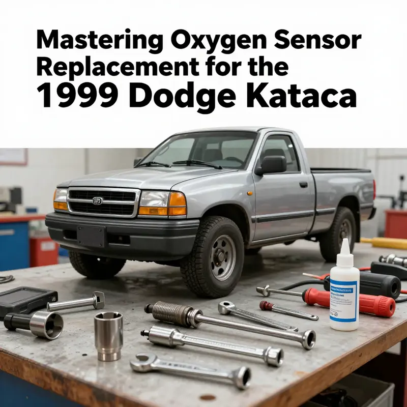
The toolkit for this job is not extravagant, but it is precise. You’ll want a wrench or socket set that includes a 7/8-inch and a 13/16-inch option, because the hex portion of oxygen sensors most commonly measures within that range. In addition, a dedicated oxygen sensor socket—a deep-well socket with a rubber insert or a flexible design—is highly recommended. These sockets grip the sensor’s hex nut without marring the sensor’s body, a crucial step when corrosion has set in. A can of penetrating oil, such as a light rust-busting spray, is invaluable if the sensor is stubbornly seized. A ratchet is needed to apply leverage, and a torque wrench is optional but strongly advised. The typical torque specification for a properly installed oxygen sensor sits around 30 to 40 ft-lbs; staying within that range protects the sensor’s internal circuitry and preserves the integrity of the exhaust threads. Don’t forget basic safety gear—gloves and safety glasses—to shield yourself from hot components and sharp edges when you work under the vehicle. If you have the opportunity, a rubberized mat or a lift can reduce the physical strain, but a solid jack and stands set also works well when used with proper safety precautions.
The actual replacement sequence is simple but requires patience and attention to cleanliness. Start by allowing the engine to cool fully; a hot exhaust can cause severe burns and complicate the removal of a stubborn sensor. Locate the sensor by tracing the exhaust pipe toward the engine up near the manifold area for the upstream unit, or after the catalytic converter for the downstream sensor. Disconnect the electrical connector first, carefully releasing any locking tab. This is a common failure point; a connector that won’t release or a pin that pulls out of the harness can create confusion about sensor condition. If the connector resists, apply a small amount of penetrating oil around the base of the plug to ease entry, but avoid getting any oil inside the electrical contacts. Once the connector is disengaged, apply penetrating oil to the sensor’s base to help with loosening if rust is present. Use the oxygen sensor socket with a ratchet to unscrew the sensor; go slowly to avoid cross-threading the sensor or damaging the exhaust pipe threads. When the old sensor comes free, inspect the threads and the gasket surface for any signs of damage or warping. Install the new sensor by hand first to check alignment, then tighten to the manufacturer’s torque specification. Reconnect the electrical plug, making sure the lock engages fully and the wires aren’t stretched or pinched. If a new gasket accompanies the sensor, install it according to the instructions that come with the unit. A good seal matters for preventing exhaust leaks, which can skew sensor readings and fuel trims even with a new sensor in place.
With the mechanical side finished, focus shifts to the engine’s electronic side. Clear any fault codes with an OBD-II scanner and take the Dakota for a short drive to let the ECU relearn the system. The learning process is not instantaneous; it relies on a series of steady driving conditions to reestablish baseline fuel trims and sensor response across different temperatures and loads. If the check engine light returns, recheck the sensor’s electrical connection and the sensor’s position. Sometimes a code will linger if there is a secondary issue such as an exhaust leak, a misfire, or a vacuum leak that continues to alter the air-fuel ratio. In those cases, the root cause lies outside the sensor and must be addressed before the system can settle back into normal operation. This is a practical reminder that the Dakota’s emissions and performance depend on a chain of reliable components, and one faulty link can mislead the whole system. If you need model-specific guidance for steps and torque values, consult trusted service manuals or automotive resources that provide procedures tailored to the 1999 Dakota and its exact exhaust configuration. In the broader sense, the journey from diagnosing a sensor fault to completing a successful replacement is a disciplined blend of mechanical precision and electronic understanding. The job benefits from planning, a calm approach to removing stubborn hardware, and a commitment to a proper seal and secure electrical connections. While this chapter has focused on the tools and the process, the deeper takeaway is that replacement—properly executed—restores the feedback loop and supports better fuel economy and lower emissions, which in turn protects the catalytic converter and the vehicle’s long-term health. For readers seeking more granular, model-specific procedures, trusted manuals and online resources can provide the step-by-step nuances that sometimes differ from vehicle to vehicle. And for those considering the broader financial aspect of ongoing repairs, the link above offers guidance on budgeting for routine truck maintenance, encouraging a proactive mindset. External guidance from dedicated repair resources can be invaluable when you want confidence that you’re following the correct sequence and torque ranges for your Dakota’s specific build. For a model-specific service perspective, consult comprehensive automotive manuals or professional repair databases available online: https://www.alldatadiy.com/.
From Diagnosis to Replacement: Installing the Oxygen Sensor on a 1999 Dodge Dakota for Reliable Mileage

When a 1999 Dodge Dakota throws a check engine light, the instinct to “tweak” the sensor can be strong. Yet the reality you’ll reach quickly is this: oxygen sensors are not meant to be repaired in most cases. They are small, highly precise electronic devices that live in a harsh environment where heat, fuel mixture, and exhaust chemistry constantly challenge their surfaces and elements. Once the internal ceramic element has degraded or the heater circuit fails, cleaning or attempting a field repair does little to restore accuracy. The consequence, more often than not, is a gift-worried orbit of uncertain readings and a wear-prone engine management system that continues to chase a faulty signal. For many Dakota owners, the simplest and most reliable path is to replace the sensor rather than try to coax it back to life. The diagnostic codes that commonly accompany a failing oxygen sensor—ranging in the P0130 to P0141 family—point to real sensor problems rather than a mysterious vacuum leak or a misfire elsewhere in the system. The moment those codes appear, the door opens to replacement as the prudent course. The Dodge Dakota from 1999 schedule typically includes two oxygen sensors: the upstream sensor, which sits before the catalytic converter, and the downstream sensor, located after the cat. If the code speaks to Sensor 1, that is the upstream unit; Sensor 2 is the downstream one. The distinction matters because the two sensors have different roles in the engine’s self-learning loop, and misdiagnosing which one is failing can lead to unnecessary work or misinterpretation of the readings. A replacement, when performed with care, restores the feedback the engine control unit depends on to tune fuel delivery and ignition timing, helping to reclaim fuel economy and reduce emissions. In this context, the repair philosophy shifts from “repair what’s broken” to “replace with a sensor that meets or exceeds OEM specifications and let the computer relearn.” It’s a practical pivot that aligns with how modern emission control systems are designed to operate, and it avoids the disappointment that can follow a failed repair attempt.
Before you even touch a wrench, preparation becomes the quiet engine of the whole job. You’ll confirm the correct sensor configuration for your engine choice within the Dakota’s lineup—whether you’re dealing with the 3.9L V6 or the 5.2L V8, each uses its own sensor arrangement and mounting location. With the two sensors in mind, you’ll choose a replacement that is either OEM-equivalent or a high-quality aftermarket unit engineered for long-term reliability in exhaust conditions. The process hinges on a few fundamental tools and a respect for the heat-soaked environment you’re about to disturb. An oxygen sensor socket, typically sized for the sensor’s hex head, is essential. You’ll also want penetrating oil if the sensor base has corroded or become stubborn after years of heat cycles, a normal wrench for the final snugging, and a torque wrench to reach the recommended tightness without overdoing it. The small but important detail of circuit protection—disconnecting the battery to prevent shorts while you’re unplugging and plugging connectors—sets a safety baseline that saves you from electrical mishaps or a headache later on. Safety is not a chore here; it’s a practical safeguard against burns, electrical shocks, or misrouted wires that can rattle around hot exhaust components during the reassembly.
The actual replacement is a careful sequence designed to preserve threads, seal integrity, and sensor electronics. You locate the upstream sensor near the exhaust manifold, as close to the engine as the pipe geometry allows, and the downstream sensor further along the exhaust path, after the catalytic converter. The path to each sensor often requires a passport through the undercarriage or a small amount of engine bay contortion, especially for the downstream unit. Once you identify the sensor, you’ll unplug its electrical connector with a steady finger and a gentle tug on the housing, avoiding strain on the harness. The lock tab on the connector is usually the key to a clean release. If the sensor shows its age by rust or being stubborn in place, a light spray of penetrating oil around the base can help, but you’ll want to let it soak briefly before trying again. Then comes the removal itself: fit the correct O2 sensor socket onto the sensor’s head and apply measured force to loosen. A breaker bar can be a lifesaver when corrosion or heat cycling has stubbornly fused the threads. You’ll remove the old unit with even, controlled pressure, taking care not to spin the exhaust pipe or nick the threads. When the old sensor clears, you’re ready to prepare the mounting surface for the new one.
Cleaning the exposed exhaust threads is a step many overlook but should not be skipped. A quick pass with a wire brush or a dedicated thread cleaner removes rust flakes, old sealant residues, and debris that could otherwise compromise the new sensor’s seal. A clean surface ensures a solid base and prevents future leaks where the sensor threads into the exhaust pipe. Before you thread in the new sensor, you lightly coat its threads with a high-temperature anti-seize compound designed for exhaust systems. This coating aids future removal and helps prevent galling, especially on vehicles with frequent temperature cycling. It’s a small measure with a big payoff, but use it sparingly and only on the threads—the goal is to avoid any sealant or adhesive material entering the sensor’s sensing element. The new unit then goes in by hand, turning smoothly and aligning the threads. Once it’s fully seated, you tighten with a torque wrench to the manufacturer’s spec, which for most O2 sensors sits in a range that balances a secure seal with the delicacy of the internal components. Over-tightening is a common mistake that can crack the sensor body or strip the threads, and the consequences can echo through the engine’s fuel-management performance.
With the sensor installed, you reconnect the electrical connector and ensure the wiring harness is safely routed away from hot pipes and moving parts. A firm click on the lock tab usually confirms a good connection. The next step—clearing codes with an OBD-II scanner—brings the system back to a known starting point. If the check engine light had been lit due to the old sensor, clearing the stored codes is essential because the ECU may still hold the old fault in its memory. After that, you’ll start the engine and let it idle for several minutes as the sensor warms up and begins to feed data to the control module. Drive the Dakota through a short normal-driving cycle so the ECU can run its self-diagnostic routines and re-learn the correct air-fuel mixture for the new sensor. It is entirely normal for the first few drives to show minor hiccups as the engine’s learning curve resets; this typically smooths out as the ECU references the new sensor’s output.
One of the best takeaways from this process is the clarity it provides about long-term maintenance planning. If you’re undertaking a sensor replacement, it’s prudent to view it as part of a broader maintenance strategy rather than a one-off repair. The repair often dovetails with a broader inspection of the exhaust system, intake leak checks, and ignition health so that the entire fuel-management loop remains coherent. A practical consideration during planning is budgeting for routine maintenance tasks that forego surprises and keep the Dakota running efficiently over time. For readers who want a structured approach to that planning, a dedicated guide can help you balance preventive maintenance with unexpected repairs, ensuring you spend where it matters most. Budget considerations, routine inspections, and a clear path to timely replacements keep a truck like the Dakota reliable and cost-effective on the long road. See a practical outline in the linked resource below to start budgeting for routine truck maintenance, and carry that discipline forward into every repair task you tackle.
To illustrate how thoughtful planning supports repair work, it’s helpful to reflect on the broader ecosystem of tools, manuals, and professional resources. Referencing model-specific service procedures is always wise, and for those who want detailed diagrams and step-by-step guidance, trusted repair manuals and platforms provide the blueprint you need. These resources reinforce the idea that a careful replacement, done with the right tools and the right approach, can restore the Dakota’s performance without chasing the myth that a sensor can be repaired in the field. You’ll also find that professionals advocate for using OEM or OEM-equivalent sensors and avoiding temporary makeshift fixes that can mask a real problem or degrade the catalytic converter over time. As you finish the job, recheck the system’s readiness monitors with your scanner and confirm that your chosen sensor is reporting data within expected ranges across a drive cycle. If readings are erratic or the light reappears, recheck the electrical connections and the sensor’s seating torque, then consider a second scan to confirm that the ECU has accepted the new sensor and has begun the re-learning process. This practical approach ensures you’re not chasing a symptom but addressing a genuine replacement that supports overall engine health.
In closing, the Dakota’s oxygen sensor replacement is a straightforward, repeatable task when approached with care and a respect for the vehicle’s design. It’s not a quick fix for every drivability issue, but when a codeset points squarely to a faulty sensor, replacement offers a reliable return to proper engine management. The result is improved fuel economy, cleaner emissions, and the confidence that your truck will perform as designed once again. Guidance and diagrams from official service resources are invaluable if you want to confirm locations and torque specifics, and they remind us that model-specific details matter. For additional reading on model-specific procedures and diagrams, you can consult reputable repair platforms that host comprehensive manuals. Lastly, as you prepare to tackle this replacement, keep in mind the broader maintenance framework that will help your Dodge Dakota stay on the road. Budgeting for routine truck maintenance is a practical habit that supports every repair decision and sustains the truck’s value and reliability over time. Budgeting for Routine Truck Maintenance.
External resources can also deepen your understanding of the service approach. If you want to cross-check model-specific instructions or verify torque values and procedure steps against a widely used reference, consider consulting AllData DIY for detailed diagrams and official procedures tailored to your 1999 Dodge Dakota. This external guide provides a authoritative baseline to compare against your own notes and the vehicle’s subtle signals, ensuring you’re aligned with industry practices as you replace the sensor and reestablish the Dakota’s engine-management discipline. For more extensive model-focused guidance, visit https://www.alldatadiy.com and explore the sections that cover the oxygen sensor replacement procedure and related diagnostic steps. By keeping this information at hand, you can approach the replacement with confidence, knowing you’re following a methodical, standards-driven path that supports long-term engine health and cleaner exhaust.
The installation experience, then, becomes more than a task; it becomes a deliberate practice in maintenance. The Dakota’s sensor replacement teaches patience, attention to electrical connections, and respect for the exhaust system’s heat and complexity. It reminds us that while the sensor itself is a relatively small component, its role in the engine’s feedback loop is outsized. If you approach the job with a plan, you’ll finish with a repaired system rather than a patched symptom, and you’ll set your Dakota up for reliable performance on countless miles to come. The road ahead is smoother when the sensor’s data feeds the ECU accurately, guiding fuel delivery, ignition timing, and emissions control with the clarity that a properly replaced upstream or downstream sensor can provide.
Replacing Rather Than Repairing: A Practical Guide to Oxygen Sensor Failures on a 1999 Dodge Dakota

Replacing Rather Than Repairing: A Practical Guide to Oxygen Sensor Failures on a 1999 Dodge Dakota
When the dash light flickers and the exhaust starts to smell a little richer or harsher, the O2 sensor often takes center stage in the drama of modern fuel management. For most owners of a 1999 Dodge Dakota, the reality is straightforward: oxygen sensors are not typically repaired. They are service items designed to be replaced when they fail or degrade. Yet understanding how these sensors influence the truck’s behavior helps you decide the right path—fix, replace, or defer until it’s essential. The oxygen sensor is a small probe with a big job. It sits in the exhaust stream, constantly measuring the amount of oxygen in the exhaust gas after combustion. That information is fed back to the vehicle’s Engine Control Unit (ECU), which uses it to tune the air-fuel mixture in real time. The goal is a stoichiometric balance, roughly 14.7:1 air to fuel for many gasoline engines, a balance that minimizes pollutants while preserving power and economy. When this feedback loop runs smoothly, the engine breathes efficiently, the catalytic converter works as designed, and emissions stay within legal limits. When the sensor begins to drift, however, the ECU loses its footing. It may read a lean condition even when the engine actually has enough fuel, or it may see a rich signal that doesn’t reflect the true air entering the cylinders. Either scenario pushes the ECU to adjust fuel delivery in ways that can undermine performance and efficiency.
The Dakota you drive is equipped with two O2 sensors: the upstream sensor (Sensor 1) before the catalytic converter and the downstream sensor (Sensor 2) after it. When the vehicle’s onboard diagnostic system detects a problem with one of these sensors, it stores a diagnostic trouble code (DTC), commonly in the P0130–P0141 range for O2 sensor circuits. Those codes guide the diagnosis toward the faulty sensor, but they are not the final arbiter of repair. Sensor health can be impacted by age, heat, oil leaks, or contamination, and the fix is often straightforward: replace the sensor rather than attempt a repair that leaves underlying failure unresolved.
What follows is less a tech manual and more a practical orientation to what a failed sensor means for your Dakota and how to approach the repair with clarity. The consequences of a failing O2 sensor extend beyond a single malfunction. Fuel economy can drop as the ECU relies on pre-programmed maps rather than real-time feedback. Emissions can rise, pushing exhaust readings past permitted limits and making the truck more likely to fail inspections where required. Drivability can suffer in subtle but meaningful ways—rough idle, hesitation on acceleration, or a general sense of the engine not responding crisply in daily driving. The check engine light is the overt signal that something in the sensor’s signal path is out of spec or out of switching activity. It is a warning that should not be ignored, because continued operation with a faulty sensor can allow the catalytic converter to overheat or degrade more rapidly over time, compounding repair costs.
From a repair perspective, the guidance is consistent: do not attempt to “patch” a broken O2 sensor with cleaning or makeshift fixes. Cleaning sensors is rarely effective, and trying to restore a sensor through nonstandard methods rarely yields lasting improvement. A new, properly installed sensor restores the ECU’s ability to regulate fuel in real time, reducing emissions, stabilizing idle, and helping the engine perform as designed. This is especially important in a 1999 Dakota, where the emissions and fuel systems are older and more susceptible to the cumulative effects of an undervalued sensor. When a fault is traced to Sensor 1, the upstream sensor, replacement is typically the quickest path back to normal operation. If the issue points to Sensor 2, the downstream sensor, replacement still remains the reliable solution. The key is ensuring you purchase the correct sensor for the Dakota’s configuration and that installation follows the maker’s guidelines for a secure electrical connection and proper thread engagement.
A practical approach begins with precise identification. The two sensors have distinct positions and roles, and the diagnostic codes often point to Sensor 1 when a code mentions Bank 1 Sensor 1. With the correct sensor in hand, the replacement process becomes a measured sequence rather than an improvisation. The choice between OEM parts and high-quality aftermarket equivalents is part of a broader discussion about durability and long-term performance. For the upstream sensor in particular, common aftermarket options align with the needs of a 1999 Dakota, but compatibility and build quality matter just as much as price. The goal is a part that withstands heat, resists contamination, and provides a clean, stable signal to the ECU over tens of thousands of miles.
The actual replacement steps are straightforward in concept, though they do require care and the right tools. Start by allowing the engine to cool completely so you can safely handle the exhaust system. Locate the oxygen sensor, which sits in the exhaust stream near the exhaust manifold for the upstream Sensor 1, and further along for Sensor 2. If the sensor is stubborn, apply penetrating oil and let it soak briefly. Use the appropriate socket—typically a specialized oxygen sensor socket, about 7/8 inch or 22 millimeters—and work the sensor loose with steady, even pressure. When removing the old sensor, be mindful of any worn wiring harness plugs that connect to the sensor; these should unplug cleanly without forcing.
With the old sensor out, prepare the new unit. Hand-tighten the sensor to the exhaust pipe or manifold threads to avoid cross-threading, then bring it to snug with a wrench. Do not overtighten, as excess torque can damage the sensor or the exhaust flange. Reconnect the electrical connector, ensuring a secure, click-in fit. After installation, it is prudent to clear any fault codes with an OBD-II scanner. The vehicle will then need to drive through a relearn period so the ECU can adapt to the new sensor’s signal. This relearn process is crucial; without it, you may observe a transient period of imperfect fuel trim as the system calibrates. In many cases, a short highway drive and a few city miles suffice for the ECU to settle into the new baseline. If you have ongoing concerns about sensor heating, ground circuits, or wiring integrity, a professional inspection can confirm the harness integrity and ensure that the sensor’s signal path remains clean.
The practical takeaway is simple. Replacing—a new upstream Sensor 1 or downstream Sensor 2—is the dependable path to restoring proper air-fuel balance and keeping emissions in check. There is no reliable shortcut through cleaning or reconditioning. The parts you choose should be authentic or quality aftermarket, and the installation should be performed with attention to the sensor’s orientation and its electrical connection. After you’ve completed the replacement and cleared the codes, take a careful drive that includes both steady cruising and some acceleration to confirm the system’s proper operation. If the check engine light reappears or if the fuel economy remains stubbornly poor, it is wise to recheck the sensor’s fitment, the wiring, and the connector, or consult a technician who can perform a more thorough diagnosis, including verifying the sensor’s response time and its voltage output across various operating conditions.
Beyond the immediate repair, a broader view of maintenance helps extend the Dakota’s reliability. Regular inspection of exhaust leaks, manifold gaskets, and sensor wiring can prevent nuisance faults from escalating into a diagnostic headache. Keeping the intake clean and ensuring there is no oil or coolant intrusion into the exhaust stream helps preserve sensor life. If you are uncertain about the exact sensor location or the model-specific wiring harness on your Dakota, consult the official service manual or trusted repair databases. These resources provide step-by-step procedures tailored to your vehicle, reinforcing the general approach with model-specific torque values and connector configurations. When you plan a repair, it helps to keep a simple checklist in mind: identify the correct sensor (upstream or downstream), purchase a compatible unit, use the proper socket and hand-tighten before final torque, reconnect the harness securely, and allow the ECU to relearn after code clearing. The goal is a smooth restoration of performance, economy, and compliance with emissions standards.
For readers who want a deeper dive into model-specific procedures, reputable repair references offer detailed guidance, diagrams, and torque specifications aligned with your Dakota’s engine and exhaust layout. They emphasize that while the concept of replacing an oxygen sensor is straightforward, the reliability of the repair hinges on using a sensor that matches the vehicle’s design and on performing the installation with care. In practice, approaching the job with patience and a respect for the sensor’s role in the emissions system yields the best long-term results. If you need broader context on maintenance practices that reinforce sensor longevity, consider looking into the in-house truck maintenance resources that cover routine upkeep and systematic diagnostics—these can help you build a practical plan for ongoing care of a legacy truck like the 1999 Dakota. For a broader maintenance perspective, see the in-house truck maintenance guide.
In closing, the oxygen sensor is a small device with a big impact on how your Dakota runs, feels, and breathes. Its life cycle is one where “repair” rarely offers a durable outcome; replacement provides a reliable path back to efficiency and cleanliness. When the sensor fails, the smart move is to replace it, confirm the sensor’s integrity and wiring, clear codes, and allow the ECU to relearn. That approach protects your wallet by preserving fuel economy and protecting the catalytic converter from damage that can be costly to repair. The Dakota, like many long-lived trucks, rewards this disciplined approach with smoother performance and reduced emissions over the miles ahead.
External reference for further detail on service manuals and diagnostic guidance: https://www.alldatadiy.com/
Final thoughts
Ensuring the efficient operation of your fleet depends significantly on maintaining each vehicle component, notably the oxygen sensor in your 1999 Dodge Dakota. Through proper identification, procurement, and installation processes for the oxygen sensor, you can enhance vehicle performance, maintain regulatory compliance, and avoid costly repairs down the road. This article aimed at fleet managers, trucking company owners, and related professionals underlines the importance of reacting promptly to sensor failures, thus safeguarding your fleet’s operational efficacy and longevity.