Cracked truck frames present serious challenges for fleet managers, trucking company owners, and heavy equipment operators. A compromised frame can significantly affect vehicle performance and safety, leading to operational disruptions and costly repairs. This comprehensive guide aims to equip industry stakeholders with the necessary knowledge to accurately assess and diagnose frame cracks, deploy effective welding repair methods, implement reinforcement strategies, explore frame replacement options, and ensure rigorous post-repair verification processes. Each chapter is designed to address specific aspects of cracked frame repair, providing actionable insights to enhance safety and reliability in heavy-duty vehicle operations.
Diagnosis as the Gatekeeper: A Thorough Assessment of a Cracked Truck Frame Before Repair
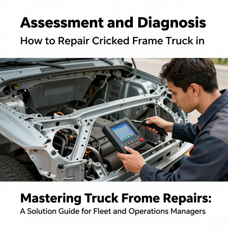
The frame of a heavy-duty truck is more than a backbone; it is the living structure that carries every load, absorbs road irregularities, and maintains alignment across the drive train and suspension. When a crack appears in that frame, the simplest instinct—patch it and press on—rarely yields a safe, long-lasting solution. Diagnosis is not a preface to repair; it is the essential checkpoint that defines whether a repair is feasible, and if so, which method will restore true structural integrity. A systematic assessment blends eyes, measurements, and science, aligning practical field observations with laboratory-grade testing to map a crack’s scope, its impact on geometry, and its potential progression under load. Only through this disciplined process can operators avoid a false sense of safety and invest in a repair that stands up to real-world demands.
The diagnosis begins with what seasoned technicians call the sandwich of certainty: visible signs on the outside, measured distortions in the frame’s geometry, and hidden flaws that only advanced testing can reveal. Visual inspection is not decorative; it is the first filter that separates routine wear from critical cracking. Look along the main frame rails, crossmembers, and mounting points where high stress concentrates. Cracks often radiate from fastener holes, welds, or corners near suspensions and cab mounts. Dents, bends, or kinks in the rails can indicate a distortion that has silently redistributed stress across the entire chassis. In these moments, the decision to keep looking—rather than conclude—becomes the turning point between a repair and a replacement.
To move from visual clues to a defensible conclusion, dimensional assessment follows. A straight edge or a laser alignment tool can reveal whether the rails stay true to their intended plane and spacing. Warpage may be subtle: a few millimeters of bow across a long rail or a misalignment in a crossmember could propagate into steering or alignment faults once the vehicle is loaded. In practical terms, technicians compare factory specifications and measure gaps between wheels and fenders, axle housings, and mounting surfaces. The “find a line” and “measure gap” approaches referenced in field diagnostics are not tricks; they are time-honored methods for spotting distortions that standard inspections might overlook. If a line drawn along a frame rail shows uneven heights, or if the wheel-to-wheel measurements drift outside tolerance, those metrics become red flags for deeper investigation.
Beyond visual and dimensional checks, the operational truth of the frame emerges only when the vehicle is put to work in controlled conditions. Dynamic and operational diagnosis asks, in effect, what the frame does under real loads and movements. A careful test drive on varied surfaces—highway smoothness, rough back roads, and urgent braking sequences—can reveal vibrations, steering wander, or pull that does not align with wheel or tire issues alone. Listen for metallic clunks, creaks, or changes in suspension response that correlate with steering inputs or bump events. Abnormal noises and unexpected handling symptoms often hint at misalignment, localized failure, or mounting point degradation caused by a cracked span. The takeaway is not that a crack automatically explains every symptom, but that the symptom set becomes a map to the crack’s influence on the frame’s geometry and the vehicle’s dynamic stability. Tire wear patterns, uneven ride heights, or loose, rattling components can be indirect indicators of frame distortion that deserve closer, more precise inspection.
When the surface signs and road-tested symptoms point toward a potential crack, professional non-destructive testing (NDT) is the decisive layer. This is where the assessment transcends what can be seen with the naked eye and what can be inferred from test drives. Ultrasonic testing (UT) penetrates into the body of the metal to reveal internal flaws, delaminations, or voids that lie beneath the surface. It provides a precise map of crack depth and location, information that is critical when evaluating whether a crack can be cured by welding or whether it heralds weakness beyond repair. Magnetic particle inspection (MPI) serves as a complementary method for ferrous frame materials, highlighting surface and near-surface discontinuities that might escape other tests. Together, these techniques render a verdict that aligns with engineering reality rather than hope. In many cases, the results dictate a conservative path: repair only when the material’s integrity can be restored with sufficient margin, or prepare for a replacement when defects undermine essential load paths.
The decision framework that follows NDT is grounded in safety and engineering judgment. Minor cracks located in non-load-bearing segments may be candidates for weld repair and selective reinforcement, provided the area remains within the design’s tolerance for residual stresses and geometric distortion. Yet critical cracks demand much more caution. Cracks at mounting points, major cross-members, or along the main rails that carry suspension loads typically signal unrecoverable risk—load paths can be compromised, and a repair that masks the flaw could fail catastrophically under service. The judgment thus hinges on the crack’s location, size, and the surrounding stress environment, not just on whether a crack can be welded shut. When repair is considered, it must be evaluated against the possibility and consequences of residual stress, heat-affected zone brittleness, and the risk of crack re-initiation. The most reliable path to safety in this context often points toward replacement of the affected frame segment or the entire frame, especially if the original specifications—material grade, dimensions, and structural properties—cannot be perfectly matched in a repair.
Throughout diagnosis, standards and procedures provide the yardsticks by which decisions are measured. Industry best practices emphasize controlled heat input during welding to minimize distortion and avoid overheating the surrounding metal, a principle that preserves the frame’s overall toughness. They also warn against cold working after welding—hammering or bending a repaired area can introduce new brittleness and crack initiation sites. Quality control, ideally performed by certified technicians, demands inspection by qualified personnel who can verify weld integrity to applicable codes and standards. This is not optional caution; it is a fundamental requirement for ensuring that a repaired frame remains reliable under dynamic loads and over time.
As the diagnostic narrative unfolds, it helps to remember the broader context: the Federal guidelines and regulatory expectations that govern frame repairs. The emphasis is on safety, traceability, and documented compliance. The diagnostic phase doesn’t only determine whether a crack exists; it defines the path forward—whether the frame can be repaired in a way that preserves safety margins or whether replacement is the responsible course. The point is to avoid a quick fix that merely defers the problem to the next mile. The most trustworthy repairs follow a transparent sequence: precise diagnosis, lab-grade testing where indicated, alignment verification, and post-repair verification that re-establishes the frame’s dimensional fidelity and structural capacity.
The practical takeaway for fleet managers and operators is clear. Invest in a thorough assessment rather than rushing to a repair. The diagnostic stage should inform every subsequent decision, from the choice of repair method to the extent of reinforcement or the scope of replacement. It also provides the baseline needed for documenting safety compliance, an essential facet when operating within regulated environments. For readers who want to see how a well-structured, maintenance-forward approach plays out in real shops, consider exploring in-house maintenance practices from experienced teams and how they integrate rigorous inspection routines into daily workflows. Turnage & Sons in-house truck maintenance offers a practical reference point for the discipline and cadence of preventive checks, aligned with the philosophy that prevention begins with precise diagnosis. You can learn more about their approach here: https://mastertruckrepairllc.com/turnage-sons-in-house-truck-maintenance/.
In sum, diagnosis is the true gatekeeper for cracked truck frames. It blends visual scrutiny, dimensional scrutiny, dynamic testing, and professional NDT into a coherent verdict about structural safety and repair viability. When this process is done meticulously, repairs—or replacements—are grounded in engineering reality, not hope. The result is a repaired chassis that can safely bear loads, maintain alignment, and resist the next thousands of miles of vibration, impact, and stress. For practitioners, this approach also creates a framework for communicating with regulators, insurers, and customers about what was found, what it means, and why the chosen path is the only one that preserves safety and reliability over the long haul. For authoritative procedural guidance, refer to the FMCSA Vehicle Inspection Guidelines, which detail inspection procedures, tolerance limits, and the appropriate use of non-destructive testing as part of diagnosing and repairing cracked frames: https://www.fmcsa.dot.gov/regulations/vehicle-inspection-guidelines.
Welding the Road Back: Precision Repair of a Cracked Truck Frame
A cracked truck frame is not just a blemish on steel; it is a warning that the vehicle’s backbone has compromised strength and predictable performance. When a frame shows signs of a fracture, the role of the repair team shifts from routine maintenance to structural engineering. This chapter follows a tightly scripted sequence that aligns with industry practice: a careful assessment, a chosen repair strategy, and a disciplined post-repair verification. It is written for professionals who must weigh the limitations of the frame against the demands of the load, the road, and federal safety standards. While the temptation to tackle repairs in-house can be strong, the reality remains that frame restoration—especially when welding is involved—belongs to trained technicians with the tools, procedures, and certification to guarantee safety and reliability. The aim is not to disguise a defect but to restore a frame’s original strength, and with it, the confidence that the truck can be trusted to carry heavy loads without unexpected failure.
The diagnostic phase is foundational. A thorough visual inspection may reveal obvious cracks, but many fractures reside beneath the surface, invisible to the naked eye. This is where non-destructive testing (NDT) becomes indispensable. Dye penetrant testing, magnetic particle inspection, and ultrasonic testing illuminate hidden cracks and map their extent. The use of modern three-dimensional measurement systems further sharpens the assessment by quantifying distortion and establishing a precise baseline for alignment. In practice, this means technicians do not guess where the fracture ends or how far the distortion spreads. They measure, document, and chart the repair plan around concrete data. If the frame has been overloaded or bent, the plan will differ markedly from a clean hairline crack that lies within a non-load-bearing pocket. The initial evaluation also helps determine whether restoration through welding suffices or if reinforcement or even full section replacement is warranted. A reliable diagnostic phase reduces the risk of reopening the crack after a repair or, worse, failing under real-world loads.
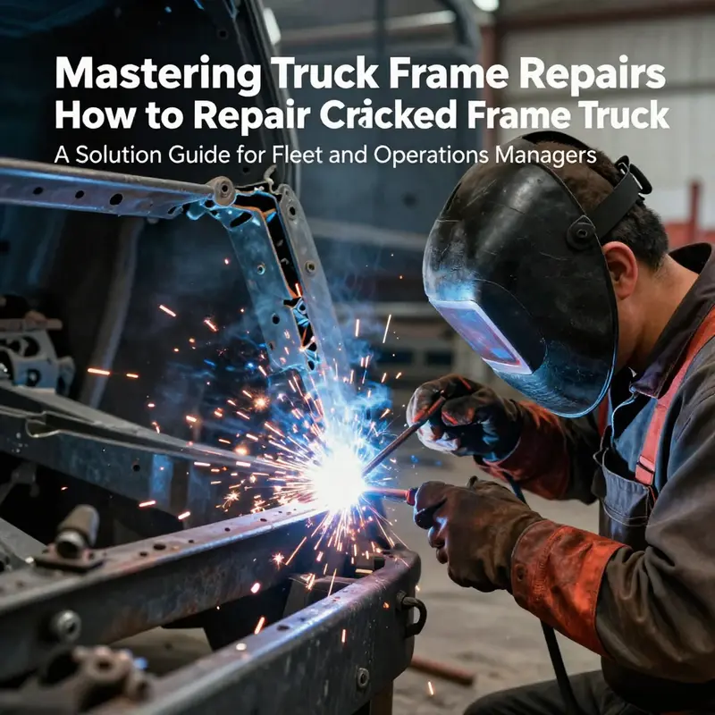
Once the crack has been characterized, the repair path emerges with greater clarity. Welding remains the most common method for restoring a cracked frame in high-strength steel, provided the crack is accessible and the surrounding material is sound enough to support weld penetration. The preparation stage is critical. The damaged area must be stripped of rust, paint, oil, and any coating that might impede weld quality. Contaminants create gaps, porosity, or weak fusion, which can undermine the entire repair. Through this stage, the principle is simple: clean metal welds clean metal. The next step involves beveling or gouging out the crack to form a smooth groove—typically a V- or U-shaped profile—so the weld metal can penetrate deeply. The groove geometry is not cosmetic; it reduces stress concentrations at the repair edge and ensures the weld fuses with sufficient depth to carry the required load. In larger or more complex repairs, a backing bar may be used behind the joint to support the weld from the opposite side. Backing bars help achieve a complete, uniform weld bead when access is constrained to one side of the frame, a situation common in heavy-truck repair.
With the groove prepared, the technician selects a welding method compatible with the frame material, thickness, and service conditions. Shielded Metal Arc Welding (SMAW) remains a robust field option for many repairs, especially when access is limited or when the repair environment is not ideal for more sophisticated equipment. Gas Metal Arc Welding (GMAW), known as MIG, offers greater control and cleaner weld beads, which can be advantageous for high-strength steels that demand tighter control of heat input. Gas Tungsten Arc Welding (GTAW), or TIG welding, is typically reserved for precision work on thinner sections or high-strength alloys where heat management is crucial to avoid warping or sensitization. The choice of filler material is equally important. Filler rods or wires must match or exceed the base material’s mechanical properties to ensure a coherent, high-strength bond. In practice, this means selecting filler material that mirrors the original frame’s material grade, or opting for a higher-strength alloy when the design requires it. The weld procedure must be designed to balance penetration, bead shape, and heat input to minimize the risk of introducing new residual stresses that could later contribute to a crack elsewhere.
Post-weld procedures play an equally vital role in the longevity of the repair. Cold cooling can trap stresses within the weld and adjacent metal, making the repaired area susceptible to future cracking. To minimize this risk, technicians employ controlled cooling, and in many cases, post-weld heat treatment (PWHT) is warranted. PWHT relieves residual stresses and can improve the toughness of high-strength steels, particularly in large repairs or when the weld encounters cyclic loading. After the weld has cooled, re-inspection with NDT methods is standard practice to confirm that the crack has been fully sealed and that no new defects have formed during the welding process. In addition to NDT, a dimensional check using 3D measurement systems provides a final verification that alignment and geometry meet the required tolerances for the vehicle’s suspension points, mounting brackets, and cross-members. This makes the subsequent reassembly of components more predictable and reduces the likelihood of misalignment that can lead to premature wear or failure.
The repair strategy may extend beyond simply filling a crack. In some scenarios, especially when the crack is near a critical junction such as a mounting point or a cross-member, structural reinforcement becomes necessary. Reinforcement involves attaching plates or brackets that rediscover stress and redistribute it away from the damaged area. These plates are welded securely, designed specifically to complement the frame’s geometry and load paths. In cases where damage is so extensive that it compromises the frame’s integrity, replacement of affected sections or even the entire frame may become the prudent course. The decision hinges on a combination of crack location, size, remaining life, and safety considerations. Replacement parts must be exact matches to the original specifications, including material grade, dimensions, and strength properties, to ensure the restored frame behaves predictably under dynamic loads.
Across all these steps, the guiding priorities remain safety, reliability, and compliance. Welding a frame is not a generic repair; it is a controlled engineering task that must adhere to established standards and be conducted by certified personnel. Excessive heat input is a common pitfall; it can soften surrounding metal, alter grain structure, and invite new cracking. Technicians manage heat with technique and discipline, delivering welds that fuse deeply without compromising the material’s properties. Cold working or post-weld hammering is avoided after welding because these practices can introduce brittleness and precipitate future failures. Each weld bead is treated as a structural element; it must be inspected and documented just as rigorously as any critical joint in a pressurized system. Quality control is not merely procedural; it is a lived standard that defines whether a road-ready repair will hold through thousands of miles of duty.
A broader context reinforces the ethical and professional stance on frame repair. Industry guidelines emphasize that frame work—especially when it involves welding or structural changes—should be performed by certified technicians using approved procedures. This is not only about regulatory compliance; it is about ensuring that a repaired frame will perform safely under real-world conditions. In practice, this translates to a comprehensive workflow that begins with accurate assessment, continues through meticulous preparation and welding, and ends with rigorous post-repair verification. The final objective is to restore, as closely as possible, the frame’s original strength and service life, while acknowledging that some situations warrant more drastic measures such as reinforcement or replacement. The careful sequencing of steps—inspection, preparation, welding, post-weld treatment, and verification—differs from casual maintenance because it treats the frame as a life-safety-critical component that must perform under heavy loads, variable weather, and demanding duty cycles.
For readers seeking a deeper dive into structural welding standards that govern repair welding of steel components like truck frames, authoritative guidance provides the foundation for all practical decisions. The Structural Welding Code for Steel (AWS D1.1) offers comprehensive standards and best practices for preheating, filler material selection, welding procedures, and inspection protocols. These standards serve as a benchmark to ensure consistency, safety, and performance across repair projects. In the field, adherence to such standards is the difference between a repair that merely patches a crack and one that genuinely restores a frame’s capacity to carry a heavy load with confidence. As part of ongoing professional development, technicians consult these codes to align their repair plans with recognized industry practice, validate their welding parameters, and document compliance for audits and fleet safety programs. Practically, this means that every welding procedure is not improvised but is supported by documented procedure specifications, weld maps, and inspection records that future technicians can review. For those who want to explore practical maintenance context beyond the repair itself, the Master Truck Repair blog offers a consolidated resource on maintenance philosophy and fleet reliability, which can be explored here: mastertruckrepairllc.com/blog/.
In summary, repairing a cracked truck frame through welding is a disciplined integration of science and craft. It begins with a precise diagnosis, transitions into a carefully engineered repair plan, and culminates in validation that the repaired frame can safely endure the rigors of service. The process prioritizes controlled heat input, proper joint preparation, correct filler material, and rigorous post-weld verification. It also recognizes when reinforcement or replacement is the safer choice. Above all, it is a reminder that frame repair is a high-stakes task that belongs to those who bring training, procedure, and a commitment to safety to every mile on the road. When done correctly, a cracked frame does not end in failure; it becomes an opportunity to restore not only a vehicle’s structural integrity but the trust that carries with it every journey on the highway.
External resource: For authoritative welding standards and detailed repair guidance, refer to AWS D1.1: Structural Welding Code — Steel at https://www.aws.org/publications/standards/aws-d11-structural-welding-code-steel
Reinforcing a Cracked Truck Frame: Practical Techniques to Restore Strength and Safety
Reinforcing a Cracked Truck Frame: Practical Techniques to Restore Strength and Safety
When a truck frame develops a crack, the repair must be more than cosmetic. The fix needs to restore the frame’s load path, remove stress risers, and deliver lasting strength. This chapter describes the structural reinforcement techniques professional shops use to return a cracked truck frame to safe, serviceable condition. It focuses on practical choices: when to weld, when to bolt, when to upgrade materials, and how to control stresses so the repair lasts.
Start by understanding the goal: redistribute loads away from the damaged area and eliminate the conditions that caused the failure. A repair that only fills a crack accepts the original weakness. Effective reinforcement combines proper preparation, the right materials, and a method suited to the fracture location and severity.
Welding reinforcement is the most common approach for frame cracks. It begins with careful preparation. Remove paint, rust, and contaminants until clean metal is exposed. Grind a bevel on the crack to create a V-groove that promotes full penetration. Match filler material to the base metal. Using a compatible or stronger welding rod ensures the weld does not become the weak link. Weld passes should be planned to control heat input and avoid warping. Use intermittent welding or backstep techniques when long welds are required. For high-strength steels, select filler rods known for ductility and toughness, not just strength.
Reinforcement plates and gussets are often combined with weld repairs. Welded plates on both sides of the rail spread the load across a larger area. Gussets—triangular plates placed at junctions—are ideal where the crack approaches a mounting point or cross-member. Properly designed gussets reduce bending and peel stresses at the joint. Plates should be of adequate thickness to carry loads without creating new stiffness mismatches. A good rule is to use a plate thickness equal to or greater than the adjacent frame material when the repair serves a load-bearing function.
Bolted plate reinforcement is an excellent alternative where welding is impractical or forbidden. Thick patch plates, typically 1/4″ to 3/8″ thick, are precision cut to fit the rail contour. High-strength bolts in a carefully planned pattern clamp the plate and transfer shear and bending forces around the damaged zone. Bolting avoids the heat distortion welding can cause. It also allows for future removal or inspection. When using bolted plates, tighten bolts to specified torque values and use lock washers or thread-locking methods to prevent loosening under vibration. Countersinking or adding backing plates can prevent stress concentrations around bolt holes.
Structural adhesive bonding is useful as part of a hybrid strategy. High-performance adhesives can bond a reinforcing plate where welding would be difficult. Adhesives distribute stresses across the bond line and reduce localized bearing loads. However, adhesives alone are rarely sufficient for primary frame repairs. They work best in conjunction with bolting or welding, or where the plate serves a secondary support role. Ensure surface prep and adhesive selection match operating temperatures, chemicals, and fatigue loads the vehicle will face.
Stress-relief techniques are critical. Welding can introduce residual stresses that concentrate near the repair and can spawn new cracks. Controlled preheating and post-weld heat treatment (PWHT) reduce these stresses. In many heavy-duty applications, PWHT is required to meet industry standards. Follow recommended temperature profiles and cooling rates for the specific steel grade. Avoid cold hammering or aggressive bending after welding; these actions can introduce brittle zones.
Design and material upgrades pay dividends when cracks recur. Engineers often address recurring failures by changing geometry to reduce stress concentrations. Adding material where the frame was thin, adding radiused transitions instead of sharp corners, or relocating holes away from high-stress zones removes the root cause. Upgrading to higher-performance steel grades improves fatigue life, but requires compatible welding consumables and process controls. Any design modification should be validated with stress analysis or real-world testing.
Inspection and non-destructive testing must guide every reinforcement job. Dye penetrant or magnetic particle testing reveals hairline cracks that visual checks miss. Ultrasonic testing locates internal flaws or lamination. After reinforcement, repeat inspections confirm weld integrity and detect any adjacent cracking. Dimension checks ensure the frame remains within alignment tolerances. A dynamic load test, where feasible, offers confidence that the repair handles real-world stresses.
Quality control and documentation are not optional. Follow welding standards and procedures appropriate for structural steel. Record filler types, heat inputs, preheat and post-weld temperatures, and inspection results. If regulatory compliance applies, use certified technicians and maintain traceable records. This practice protects the fleet and provides evidence that repairs met professional standards.
Practical considerations determine which technique is best. Use welded repairs when access is good and the technician can control heat input. Choose bolted plates when welding is restricted or when minimal distortion is vital. Combine adhesives with mechanical fastening for corrosion resistance or where smooth external surfaces are needed. Always consider the load path: the repair must restore continuous, predictable load transfer in bending, shear, and torsion.
Think about long-term maintenance. Reinforced areas should be protected from corrosion with suitable coatings or sealing systems. Fasteners must be checked during routine maintenance intervals. Reinforcement plates and gussets should not obstruct inspection access or interfere with other systems. Train maintenance staff to look for early signs of fatigue near repaired sections.
When reinforcement cannot restore safe service, favor replacement. Replace the affected frame section or the entire frame if necessary. Replacement ensures original design properties and eliminates uncertainty. When replacing parts, match material grades and dimensions exactly. Use manufacturer specifications for weld procedures and torque values for fasteners.
If you manage a fleet, integrate reinforcement strategies into maintenance planning. Prioritize inspections for older vehicles and those with high duty cycles. Consider building a contingency fund to cover significant repairs. For practical guidance on in-house maintenance programs and planning, see resources on Turnage Sons in-house truck maintenance. External standards like those published by the American Welding Society provide the technical guidance needed for weld procedures and qualification: https://www.aws.org
Adopt reinforcement practices that are conservative and verifiable. The objective is not the quickest fix. The objective is a repair that restores the frame’s intended strength, preserves alignment, and endures the operational life of the vehicle. When in doubt, consult qualified structural welders or engineers to choose the safest path.
null
null
Beyond the Weld: Rigorous Post-Repair Verification for Cracked Truck Frames
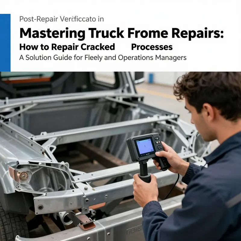
Repairing a cracked frame is only half the battle. Post-repair verification is the unseen benchmark that separates mere patchwork from a structure you can trust under the toughest loads. It translates the technician’s field skill into measurable safety, confirming that the repaired frame returns to a state that behaves as the manufacturer designed. The stakes are high: a misread weld, a slight misalignment, or a latent flaw can escalate into a catastrophic failure when the truck carries cargo, faces potholes, and negotiates long grades. Verification asks a few simple, nontrivial questions: Has every weld been saturated with enough fusion without overheating nearby metal? Do the critical mounting points sit on their original centers? And does the frame’s stiffness match the demands of the suspension and the road? The answers require a disciplined blend of testing, measurement, and validation that continues long after the last spark has cooled.
Non-destructive testing begins with a close look at what the eye cannot see. Dye penetrant inspection is often the first tool in the verification toolkit because it makes surface flaws visible without cutting or destroying the repair. The process starts with meticulous cleaning, because oil, rust, or paint will mask true indications. After cleaning, a bright dye is applied and given time to seep into any surface cracks. A developer powder is then dusted on, drawing out the penetrant from flaws and presenting them as visible lines under proper lighting. The inspector reads these indications in relation to standard acceptance criteria. Ultrasonic testing then dives deeper, using a probe to launch echoes that travel through the base metal and the weld. The returned signals map thickness, bond quality, and possible lack of fusion. In skilled hands, DPI and UT complement each other—DPI flags surface problems that UT might miss, while UT confirms whether a hidden crack exists in the heat-affected zone or the weld itself. Both require calibrated equipment, consistent procedures, and qualified technicians who can decide whether a repair passes, needs rework, or warrants a more robust reinforcement.
Dimensional verification focuses on restoring true geometry. The frame must align with its reference lines, and the centerlines of rails and cross-members must coincide within tight tolerances. A trained technician uses 3D scanners or coordinate measuring equipment to generate a digital map of the repaired area, then overlays it against the original CAD or specification data. The checks cover alignment along the entire length, straightness of the rails, and torsional rigidity, which is the frame’s resistance to twisting when the suspension encounters a bump or a shift in load. Even small deviations in wheelbase or bumper mounting can cascade into altered suspension geometry, camber shifts, or uneven tire wear. If the measurements show a bow, a twist, or a runout beyond what the structure can safely bear, adjustments may require rework. In some cases, a reinforcing plate or bracket is added to redistribute stress and restore the intended stiffness, but only after confirming the base geometry is within design limits.
Next comes an evaluation of how the repaired frame behaves under real-world stresses. A carefully designed dynamic load test subjects the frame to a sequence of loading profiles that simulate highway speeds, cargo mass, and road irregularities. The objective is to observe how the welded region and surrounding metal respond when energy moves through the structure, not just at rest. Vibration analysis supplements this assessment by identifying resonance frequencies and stress concentrations that might indicate a lingering flaw or unnoticed cracking. The result is a data-rich profile of the chassis: how it deflects, where energy concentrates, and whether the response is smooth and predictable. If the chassis exhibits excessive movement, unusual resonance, or unexpected damping, the repair is not yet ready for service, and further measures must be taken to restore safe performance.
Throughout verification, process controls matter as much as the measurements themselves. Overheating during welding can leave heat affected zones prone to cold cracking or reduced toughness, while underheating can leave weak penetrations that fail under fatigue. PWHT may be indicated for high-stress areas to relieve residual stresses created during welding. Inspectors verify that the heat history, inter-pass temperatures, and cooling rates meet established standards. They also confirm that the entire repair area was cleaned and prepared properly before testing, to minimize contamination that could skew results. The contractor or shop must adhere to proven procedures, ensuring that the weld is not only solid but that the surrounding metal remains tough and fatigue-resistant. The emphasis is on validated methods and qualified personnel, because frame repairs are not a place for improvisation or shortcuts.
After tests and measurements, documentation becomes the bridge between repair and ongoing service. Each test result becomes a data point in a repair history, with clear timestamps, equipment identifiers, and operator initials. Visual notes and NDT images accompany numeric results, all stored in a way that allows cross-checking against future inspections. This traceability matters because fatigue life is cumulative, and a repaired frame should endure the same service demands as the original structure. Operators can then compare post-repair data with baseline measurements captured before the damage occurred, if such data exist. The goal is not to prove the repair once but to demonstrate repeatable performance across a range of loads and time. In practice, teams may schedule a follow-up recheck after a period of service to verify that nothing has shifted with use or vibration. The discipline of documentation is as important as the measurements themselves, because it makes the difference between a repair that is momentary and a repair that endures.
From a decision-making perspective, verification is a risk-based checkpoint. If NDT shows no new cracks, measurements fall within spec, and dynamic tests confirm stable behavior, the vehicle can return to service with confidence in its structural integrity. If any anomaly appears, the team must weigh options: rework the weld, add reinforcement, or, in some cases, replace a frame segment. This decision is guided by safety margins, potential fatigue life, and the truck’s planned duty cycle. The process may require iterating steps—re-cleaning surfaces for another DPI pass, adjusting welding parameters, or re-stressing the area—until the data align with a clear pass criterion. While cost and downtime loom large in fleet operations, the governing priority remains the same: prevent a failure that could endanger lives or disrupt critical operations. A well-executed verification sequence converts a repair into a durable, predictable structure rather than a temporary fix.
Verification does not exist in isolation. It ties into wider maintenance practices and fleet safety programs. It becomes part of a formal safety program, linking repair data to preventive maintenance schedules and operator training. An integrated approach reduces downtime by catching issues early and guiding decisions about when a frame can safely carry heavier loads or longer journeys. The emphasis extends beyond the repair shop to the fleet office, where data-driven maintenance plans rely on consistent verification practices. For professionals exploring the topic further, the MasterTruckRepair blog offers accessible reflections on inspection routines, maintenance planning, and resilience in harsh operating environments. MasterTruckRepair blog.
Finally, the field benefits from cross-pollination with research. A rigorous study focused on chassis post-repair performance reinforces the idea that a successful repair hinges on integrating NDT, dimensional accuracy, and dynamic response. It reminds practitioners that the most robust verification programs use multiple evidence streams to validate repair quality and long-term behavior. This external perspective complements shop wisdom and provides a framework for defending repair decisions to customers, insurers, and regulatory bodies. The link to the article offers a window into methods that can be translated into practical shop workflows, guiding technicians toward more confident judgments about when a frame is truly ready for service. See the external resource: https://www.sciencedirect.com/science/article/pii/S187738951830456X
Final thoughts
Repairing a cracked truck frame is a multifaceted process that demands expertise, precision, and adherence to strict safety standards. By following the systematic assessments, appropriate welding techniques, reinforcement strategies, and replacement options outlined in this guide, fleet managers and operational leaders can restore the structural integrity of their vehicles effectively. This ensures not only compliance with safety regulations but also optimizes the performance and reliability of their entire fleet. Investing in proper repairs today leads to enhanced longevity and improved operational efficiency in the long run.